04 - 06 April
Technical
TECH TUESDAY: Analysing Ferrari’s airflow mastery
Share

The Ferrari power unit is proving to be a powerful tool, not only in the team’s cars but also when bolted into the Haas and Saubers. But don’t underestimate the long hours that Maranello’s aero engineers have been putting in at the Ferrari wind tunnel. Here, our tech aces Mark Hughes and Giorgio Piola reveal the advancements in the Ferrari floor that, barring the performance of one L. Hamilton, could well have netted them wins in Germany and Hungary...
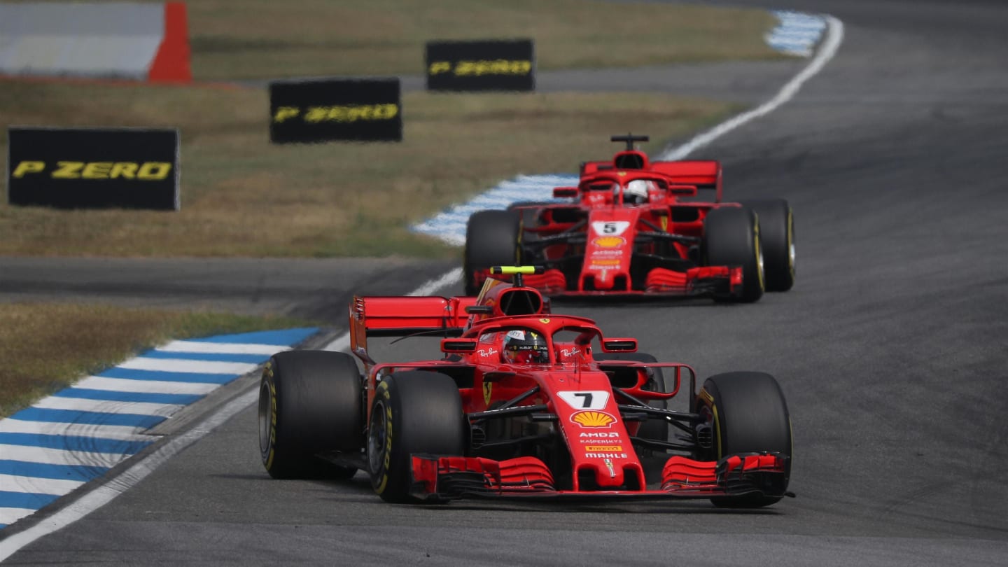
Ferrari’s recent two defeats by Mercedes in Hockenheim and the Hungaroring have been very much against the run of competitive play – and to a significant degree influenced by the weather and the virtuoso performances of Lewis Hamilton.
The Ferrari has continued to display a small but significant raw speed advantage over the Mercedes and much is being made of the apparent gains made with the Ferrari power unit, something that tallies with the Scuderia’s upswing coinciding with similar boosts in competitiveness from the Ferrari-powered Haas and Sauber cars.
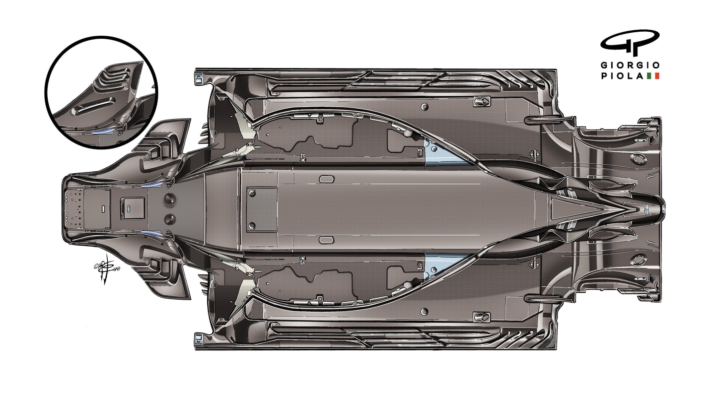
But the influence of Ferrari’s aero department should not be underestimated. The new floor introduced in Montreal proved to be a powerful one – and associated gains were still being made from the revised underfloor airflow for the next few races. It’s believed to be the most powerful single upgrade seen in the team’s tunnel for a very long time. Here we can see exactly how the floor looks from below.

The small vanes on the post-Canada floor pre-condition the airflow so that it’s less disrupted when it hits the larger vanes, which increases downforce. © Giorgio Piola
The small inset illustration shows the previous, pre-Canada arrangement of the forward mini vanes and how they contrast with those of the later floor. These small vanes were re-shaped and re-sized to better align the airflow coming through the lower part of the front suspension with the various barge boards and vanes aft of the mini vanes. They pre-condition the flow so that it arrives at the bigger vanes with less disruption, thereby creating more downforce and/or less drag.
In the older arrangement inset, you can see a pressure-relieving slot in the floor, which has been deleted in the later floor. This implies that more of the flow is being harnessed by the new mini vanes to create downforce without the need to vent the excess away because it was creating too much drag. So the forward part of the later floor would appear to be giving the underfloor air a better seal. This seems to have been key in the subsequent development, introduced at Silverstone, of triple longitudinal slots along the length of the floor in place of the previous double.
These slots perform a very different role to the small one at the front of the old floor. Their task is to create an air pressure seal by inducing vortices of spinning air at the edges of the floor. In this way, less of the airflow coming through the central part of the floor can escape out the sides and the negative pressure created by the under-floor airflow is thereby increased. The more negative pressure created, the more the car is ‘sucked’ down against its tyres, increasing its grip.
With the original mini barge board arrangement, it may have been that the vortices created by double longitudinal slots were sufficient to make an effective seal. But the new mini-board layout seems to have been so effective in increasing that negative pressure that the vortex seals were no longer strong enough to prevent leakage. Hence the move to triple longitudinal slots – and the full exploitation of the new floor that was evident in its performance at Silverstone and subsequently.
Ferrari playing with wastegate arrangements
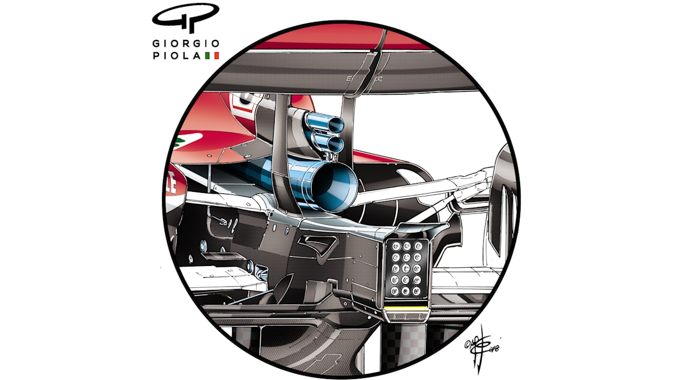
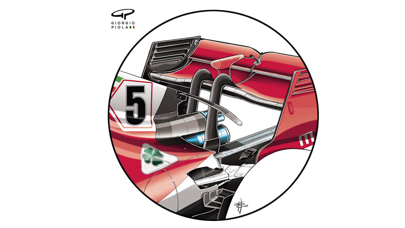
At Hockenheim, Ferrari experimented with a revised arrangement of the two wastegate pipes, moving them above the exhaust rather than having one either side. There was a corresponding change to the rear wing pillar and the bottom edge of the engine cover. The revised arrangement was used only on Sebastian Vettel’s car and only for a few laps during FP1 on the Friday. It was an experimental part, fitted only to check if readings on track equated with those in simulation and not intended to be used either at Hockenheim or Hungary.
1 / 2
In this F1 era of very limited testing, practice sessions are often the only way of testing new components. These tests have to be incorporated into the usual routine of tyre assessment and set-up work. The Ferrari exhaust arrangement was an example of this and Renault ran briefly with a shroud covering part of the bottom slot gap of the front wing. Flo-viz paint was used with both this and the standard wing on Friday, as the team attempted to correlate how the new wing – introduced the previous race, in Germany – was behaving.
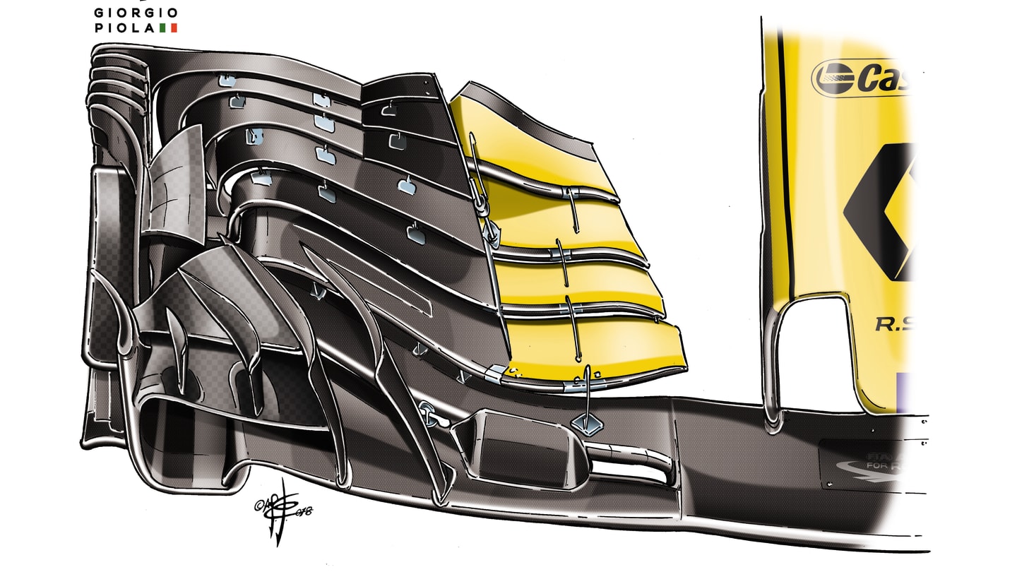
Renault unveiled their new front wing in Germany, but used Free Practice in Hungary to do further tests to see how it was working on the Renault R.S.18. © Giorgio Piola
Extra downforce and cooling on display at the Hungaroring
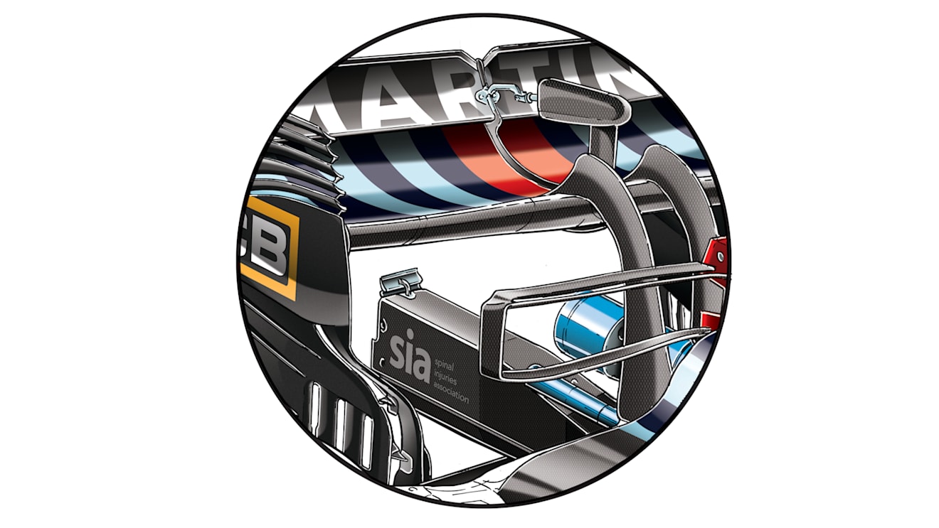
Teams also made modifications specifically for the circuit. The Hungaroring, with its very high ambient temperatures and lack of long straights, is extremely demanding of the car’s cooling – and Williams ran with the enlarged radiator cooling outlets at the back of the car which were also seen in Bahrain.
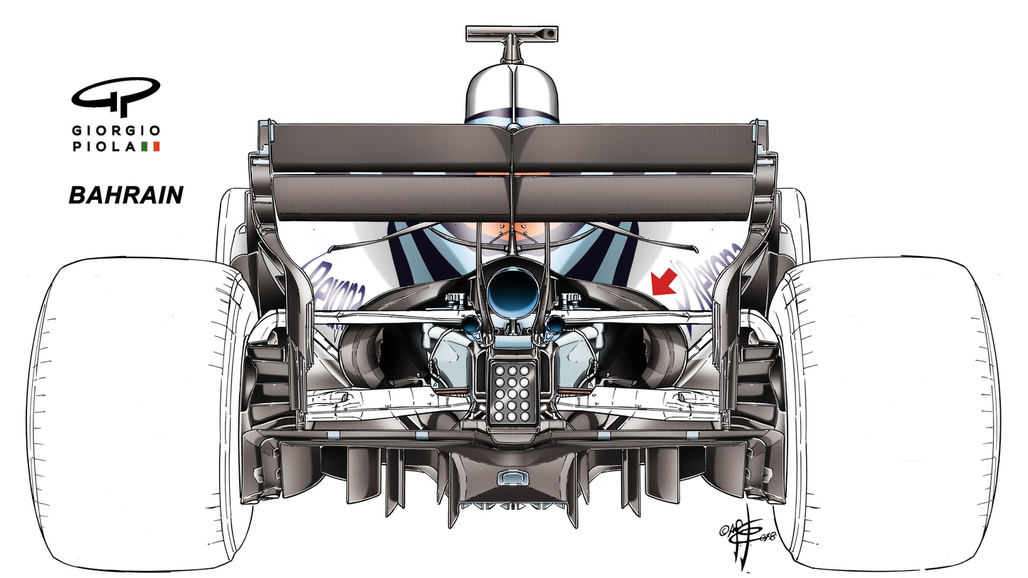
Williams called upon Bahrain-spec levels of cooling on the FW41 for the high temperatures in Hungary. © Giorgio Piola
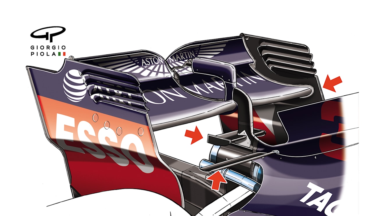
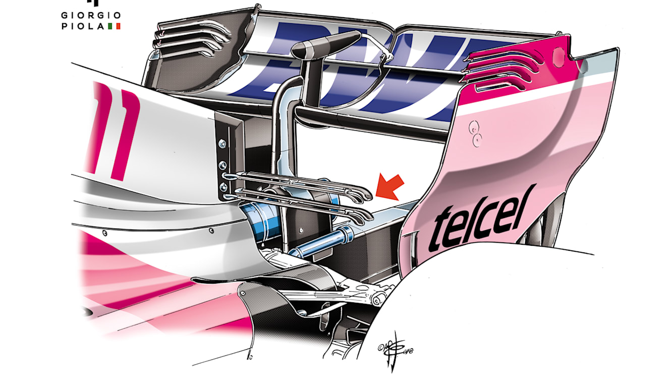
The high proportion of time spent in corners on a Hungaroring lap means downforce takes more priority than aerodynamic efficiency and Red Bull showed up with a version of their Monaco rear wing, with extended depth, monkey seat and T-wing. Force India also ran its Monaco T-wing. Williams ran a T-wing, with an extended-depth main plane, giving an increased ramp angle to the wing’s underside (i.e. more downforce). These, together with the edge of the extended radiator exit, are all arrowed in red.
1 / 3
Finally, there are the regular development pieces intended for all tracks. An example of this in Hungary was the Renault’s new Carbone Industrie brake discs, with cooling holes even down the central ridge of the disc’s width, which is there to give structural strength. This will mean the brake duct size can be reduced for a given level of brake cooling, and hence aerodynamic gains.
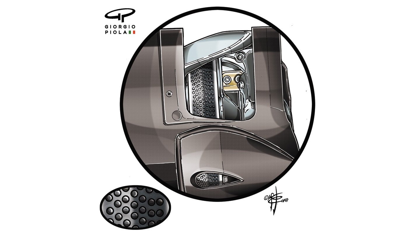
Renault used cooling holes down the central ridge of their Carbone Industrie discs. This improved brake cooling while also allowing for smaller ducts, providing aerodynamic gains. © Giorgio Piola
YOU MIGHT ALSO LIKE
Podcast F1 EXPLAINS: What it’s like to be an F1 team boss – with McLaren’s Zak Brown live in the paddock
Podcast F1 NATION: Tsunoda's Red Bull chance and the McLaren intra-team battle – it's our Japanese GP preview
Image Gallery GALLERY: Red Bull unveil special white and red livery for Japanese Grand Prix
News What tyres will the teams and drivers have for the 2025 Japanese Grand Prix?
